حمل الان ملف اعدادات اكسس بوينت الفا 1000 ملي واط (واحد واط)
مترجم من الملف الاصلي للشركة دليل تثبيت المستخدم

مترجم من الملف الاصلي للشركة دليل تثبيت المستخدم
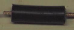
Most of the designs either had toroid magnets or a decoupler on the fly-lead of the antenna. However the location of the decoupler seems different in each design, and some designs quoted a decoupler length of 1/4 wavelength, others were !/4 wavelength times the velocity factor of the decoupler tube (brass tube quoted at 0.95). I've tried most locations and can report that without proper testing kit I can see no difference in the Signal to Noise ratio between having a decoupler and not. I decided to not bother as it simplified the design. If anyone knows a good reason why you must have a decoupler then I would love to know (especially if you know where it should be exactly). If you want to add a decoupler, please do, I found using 15mm or 22mm copper tube and a 15mm or 22mm end stop made a good design, just needing to be soldered together to get the right length, and a hole drilled in the end of the end stop to fit the cable.
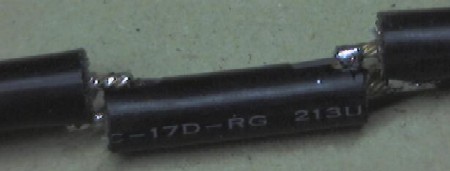
Each sector of the antenna needs to be a 1/2 wavelength long multiplied by the velocity factor of the cable. The velocity factor of RG-213 is 0.66 . If you decide to use different cable (such as LMR-400) then you need to get the velocity factor of that cable (which will be different), and recalculate all the dimensions.
                  V * C    0.66 * 299792458
1/2 wavelength = ------ = ---------------- = 0.0405m = 40.5mm
               2 * F     2 * 2441000000

V = Velocity Factor   of  RG213  = 0.66
C = speed of light = 299792458
F = Frequency of Signal = 2441000000 (middle of 2.4ghz range)
The 1/4 wave element is not adjusted by the Velocity factor, as it is in the open, so works out at just 31mm long giving a total antenna length of 355mm + fly-lead. (Thanks to Oscar for correcting me of this.)
All of the parts are available cheaply from either Maplin and any diy shop.
You don't need any special tools
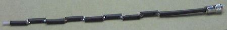
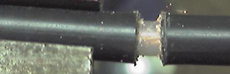
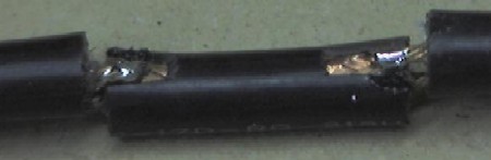
After much trial and error, I found that the neatest way to cut the cable is actually with a junior hacksaw. It gives a much cleaner finish than wirecutters. Each sector consists of a short length of RG-213 cable, with the central core sticking out each end.
When building the antenna, the exact length of each piece of RG-213 is not that important, it is the overall length of each sector that counts. I found that cutting the cable to 37mm with 6mm of core sticking out each end, gets enough overlap to easily solder the segments together. If you allow 1mm for the width of the hacksaw when cutting the sectors apart, it means you need 37 +6 +6 +1 = 50mm of cable for each sector making 8sectors + 1/4wave section come to 420 mm of cable for the antenna + cable for the fly lead.
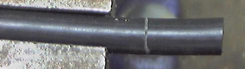
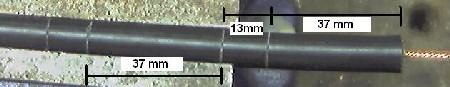
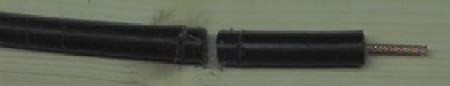
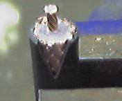
The best way to cut each sector is to make the cuts where each end of the sheathed section of the sector will be, before making the cut between each sector. The picture below shows the top 3 sections of the antenna, and the 1/4 wave section, showing the order that the cuts should be made.
The best way to make the cuts is to mark them out on the cable first. When sawing the cable it has a tendancy to deform and bend, so lightly sawing round the outside sheath first, but not cutting through, helps give a guide to the cutting for real. I use the junior hacksaw to gently saw round the cable sheath to make the mark for each section.
The first mark will be at 31mm from the end, which is for the 1/4 wave section at the top. Once you have made the mark, it is time to cut round the cable. You want to cut through the sheath, shielding, and just into the central insulation, but not into the central copper wires. You may need to practice a bit first, but you should be able to feel as you cut through the shielding into the central insulation. By leaving plenty of sheathed section either side of the cuts, the shielding stays in place when being cut.
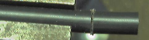
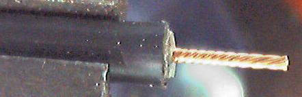
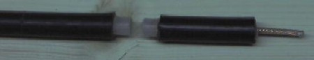
Now with pliers, gently twist off the end 31mm of sheath & shielding
This should leave the cenral insulator exposed. Using the stanley knife score round through the central insulator, but not too hard, or you will cut the central cable. Now twist off the insulation. You should be able to see the twist in the central cable through the insulation, which will show you which way to twist off the insulation, resulting in the central core twisting more tightly.
The next mark is 37mm down (68mm from end of the cable) and is the cut for other end of the sheathed section of the top sector. The next mark is 13mm down (consists of 6mm core from each sector and 1mm for cut between sectors) (81mm from end) and is the top of the sheathed section of the second sector. The next mark is 37mm down, then 13mm, then 37mm, and so on and so forth until you have each of the sheathed sections marked out.
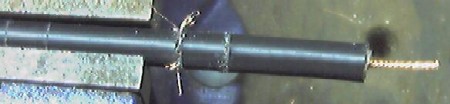
Now you are ready to cut off the top sector from the cable. You want to cut through the whole cable at the mid point of the two cuts you have just made, that is about 43.5 mm from the end of the sheath, or 74.5 mm from the end of the cable. See position 4 in the diagram above. Just saw carefully the whole way through the cable.
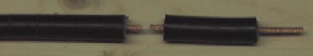
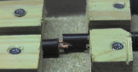
When you are readly to solder the sectors together, you need to take care , that each sector is correctly spaced. The overall length of each sector needs to be 40.5mm , measure from one end of the shielding of the sector you are adding, to the same end on the next sector, and slide the sectors together/apart until the distance is 40.5 mm. Try to get it as accurate as you can, as it affects the direction the antenna transmits in if you get it wrong. There should be a small 3mm gap between the sheaths of each sector.
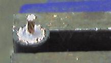
Once you have soldered each sector together, lift it up, turn it over, and move it down the clamp ready for the next sector. This results in a nice straight antenna. When soldering, remember to heat both the shielding and core so that the solder runs smoothly and fixes them together.
Once complete, test the cable with either a bulb and battery or a multimeter. The center of the fly lead should form a circuit to the 1/4 wave section, and the shield of the flylead to the shield of the top section. Now test that there are no crossed connections, by ensuring there is no circuit between the center of the flylead and the shielding of the top sector, and no circuit between the 1/4 wave section and the shielding of the flylead.
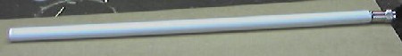
Now fix the N connector of your choice onto the end of the fly lead. The type of connector you use depends on what you want to connect to. I use inline connectors, but you could use any connector you like. Slide the antenna into a length of conduiting. It should be a snug fit, you may need to gently ease it in. Now find an old soft drink bottle top, and pop it on the top end of the antenna. Voila one complete antenna ! Securing the antenna in the conduit is best left until you are ready to mount it somewhere. You can cut 5cm slots in the bottom if the conduit, and use a jubilee clamp to grip the flylead, or drill a hole through the conduit and use a cable tie to hold the fly lead, or use a bulkhead mount connector on a botle cap, and glue it to the bottom of the conduit, or glue the flylead in place. It's up to you.
I will assume you are connecting the antenna to a wireless card in a laptop, and connecting to an accesspoint somewhere. You will need to a signal to noise meter to examine the signal strength. Most wifi cards come with software that does this. Now its time to test that the antenna actually works. This can be harder than it sounds, as unless you can remove the existing aerial from the card or ap, you can't tell it is using your new homebrew antenna. Well wrapping the existing antenna completely in 6-8 layers of tinfoil, has a dramatic reduction on signal strength, now connect the antenna, and the signal should go back up. Remember that omni antenna send out the signal horizontally, so don't test it from the room below your access point. Hopefully you should see that your new antenna actually works. There are three ways to test the gain of the new antenna
If you have a go at making this antenna, and get it working, drop me an email (address at bottom of page) and let me know how you found building it, whether you've found a simpler way, and ... be honest ... how long it took.
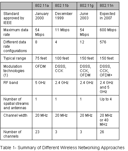
IEEE 802.11n is a proposed amendment to the IEEE 802.11-2007 wireless networking standard to significantly improve network throughput over previous standards, such as 802.11b and 802.11g, with a significant increase in raw (PHY) data rate from 54 Mbit/s to a maximum of 600 Mbit/s. Most devices today support a PHY rate of 300 Mbit/s, with the use of 2 Spatial Streams at 40 MHz. Depending on the environment, this may translate into a user throughput (TCP/IP) of 100 Mbit/s[1].
Contents[hide] |
IEEE 802.11n builds on previous 802.11 standards by adding multiple-input multiple-output (MIMO) and Channel-bonding/40 MHz operation to the physical (PHY) layer, and frame aggregation to the MAC layer.
MIMO uses multiple transmitter and receiver antennas to improve the system performance. MIMO is a technology which uses multiple antennas to coherently resolve more information than possible using a single antenna. Two important benefits it provides to 802.11n are antenna diversity and spatial multiplexing.
MIMO technology relies on multipath signals. Multipath signals are the reflected signals arriving at the receiver some time after the line of sight (LOS) signal transmission has been received. In a non-MIMO based 802.11a/b/g network, multipath signals were perceived as interference degrading a receiver's ability to recover the message information in the signal. MIMO uses the multipath signal's diversity to increase a receiver's ability to recover the message information from the signal.
Another ability MIMO technology provides is Spatial Division Multiplexing (SDM). SDM spatially multiplexes multiple independent data streams, transferred simultaneously within one spectral channel of bandwidth. MIMO SDM can significantly increase data throughput as the number of resolved spatial data streams is increased. Each spatial stream requires a discrete antenna at both the transmitter and the receiver. In addition, MIMO technology requires a separate radio frequency chain and analog-to-digital converter for each MIMO antenna which translates to higher implementation costs compared to non-MIMO systems.
Channel Bonding aka. 40 MHz is a second technology incorporated into 802.11n which can simultaneously use two separate non-overlapping channels to transmit data. Channel bonding increases the amount of data that can be transmitted. 40 MHz mode of operation uses 2 adjacent 20 MHz bands. This allows direct doubling of the PHY data rate from a single 20 MHz channel. (Note however that the MAC and user level throughput will not double.)
Coupling MIMO architecture with wider bandwidth channels offers the opportunity of creating very powerful yet cost-effective approaches for increasing the physical transfer rate.
The transmitter and receiver use precoding and postcoding techniques, respectively, to achieve the capacity of a MIMO link. Precoding includes spatial beamforming and spatial coding, where spatial beamforming improves the received signal quality at the decoding stage. Spatial coding can increase data throughput via spatial multiplexing and increase range by exploiting the spatial diversity, through techniques such as Alamouti coding.
The number of simultaneous data streams is limited by the minimum number of antennas in use on both sides of the link. However, the individual radios often further limit the number of spatial streams that may carry unique data. The  moniker helps identify what a given radio is capable of.[original research?] The first number (a) is the maximum number of transmit antennas or RF chains that can be used by the radio. The second number (b) is the maximum number of receive antennas or RF chains that can be used by the radio. The third number (c) is the maximum number of data spatial streams the radio can use. For example, a radio that can transmit on two antennas and receive on three, but can only send or receive two data streams would be
  .
.
The 802.11n draft allows up to  . Common configurations of 11n devices are
  , , and
  . All three configurations have the same maximum throughputs and features, and differ only in the amount of diversity the antenna systems provide.
PHY level data rate improvements do not increase user level throughput beyond a point because of 802.11 protocol overheads, like the contention process, interframe spacing, PHY level headers (Preamble + PLCP) and acknowledgment frames. The main medium access controller (MAC) feature that provides a performance improvement is aggregation. Two types of aggregation are defined:
Aggregation is a process of packing multiple MSDUs or MPDUs together to reduce the overheads and average them over multiple frames, thus increasing the user level data rate. A-MPDU aggregation requires the use of Block Acknowledgement or BlockAck, which was introduced in 802.11e and has been optimized in 802.11n.
When 802.11g was released to share the band with existing 802.11b devices, it provided ways of ensuring coexistence between the legacy and the new devices. 802.11n extends the coexistence management to protect its transmissions from legacy devices, which include 802.11g, 802.11b and 802.11a. There are MAC and PHY level protection mechanisms as listed below:
Even with protection, large discrepancies can exist between the throughput a 802.11n device can achieve in a greenfield network, compared to a mixed-mode network, when legacy devices are present. This is an extension of the 802.11b/802.11g coexistence problem.
To achieve maximum throughput a pure 802.11n 5 GHz network is recommended. The 5 GHz band has substantial capacity due to many non-overlapping radio channels and less radio interference as compared to the 2.4 GHz band.[2] An all-802.11n network may be impractical, however, as existing laptops generally have 802.11b/g radios which must be replaced if they are to operate on the network. Consequently, it may be more practical to operate a mixed 802.11b/g/n network until 802.11n hardware becomes more prevalent. In a mixed-mode system, it’s generally best to utilize a dual-radio access point and place the 802.11b/g traffic on the 2.4 GHz radio and the 802.11n traffic on the 5 GHz radio.[3]
Work on the 802.11n standard dates back to 2004. The draft is expected to be finalized in March 2009 with publication in December 2009,[4] but major manufacturers are now releasing 'pre-N', 'draft n' or 'MIMO-based' products based on early specs. These vendors anticipate the final version will not be significantly different from the draft, and in a bid to get the early mover advantage, are pushing ahead with the technology. Depending on the manufacturer, a firmware update may eventually be able to make current "Draft-N" hardware compatible with the final version.
As of mid-2007, the Wi-Fi Alliance has started certifying products based on IEEE 802.11n Draft 2.0.[5] This certification program established a set of features and a level of interoperability across vendors supporting those features, thus providing one definition of 'draft n'. The Baseline certification covers both 20 MHz and 40 MHz wide channels, and up to two spatial streams, for maximum throughputs of 144.4 Mbit/s for 20 MHz and 300 Mbit/s for 40 MHz (with Short Guard interval). A number of vendors in both the consumer and enterprise spaces, have built products that have achieved this certification.[6] The Wi-Fi Alliance certification program subsumed the previous industry consortium efforts to define 802.11n, such as the now dormant Enhanced Wireless Consortium (EWC). The Wi-Fi Alliance is investigating further work on certification of additional features of 802.11n not covered by the Baseline certification, including higher numbers of spatial streams (3 or 4), Greenfield Format, PSMP, Implicit & Explicit Beamforming and and Space-Time Block Coding.
In late November 2007, work on the 802.11n standard slowed due to patent issues. The Australian Commonwealth Scientific and Industrial Research Organisation (CSIRO) holds the patent to a component of the 802.11n standard. This component is also part of 802.11a and 802.11g. The IEEE requested from the CSIRO a Letter of Assurance (LoA) that no lawsuits would be filed for anyone implementing the standard. In Sep 2007, CSIRO responded that they would not be able to comply with this request since litigation was involved.[8]
| 802.11 Protocol | Release[4] | Freq. (GHz) | Thru. (Mbit/s) | Data (Mbit/s) | Mod. | rin. (m) | rout. (m) |
|---|---|---|---|---|---|---|---|
| – | 1997 | 2.4 | 0.9 | 2 | ~20 | ~100 | |
| a | 1999 | 5 | 23 | 54 | OFDM | ~35 | ~120 |
| b | 1999 | 2.4 | 4.3 | 11 | DSSS | ~38 | ~140 |
| g | 2003 | 2.4 | 19 | 54 | OFDM | ~38 | ~140 |
| n | 2009 | 2.4, 5 | 74 | 248 | ~70 | ~250[9] | |
| y | 2008 | 3.7 | 23 | 54 | ~50 | ~5000 |
There are more router products being manufactured based on the new wireless technology, known as 802.11n. وهناك مسار اكثر المنتجات المصنعه على اساس التكنولوجيا اللاسلكيه الجديدة ، المعروفة باسم 802.11n. It is a revolution from 802.11g wireless technology with some enhancements such as MIMO (Multiple In Multiple Out) that can aggregate the throughput further beyond the maximum bandwidth with current 802.11g technology. وهي ثورة من التكنولوجيا اللاسلكيه 802.11g مع بعض التحسينات مثل mimo (متعددة في العديد من أصل) التي يمكن ان تجميع مزيد من الناتج يتجاوز الحد الاقصى الحالي مع عرض النطاق الترددى 802.11g التكنولوجيا. In order to set a benchmarking standard, octoScope has recently conducted test cases based on few available draft 802.11n certified products in both office and home environment. من اجل وضع المعايير القياسيه ، octoscope التجارب التي اجريت في الاونة الاخيرة الحالات القليلة المتاحة على اساس مشروع 802.11n المنتجات المرخصه في كل من المكتب والمنزل والبيئة.
The products that were involved in the testing include Netgear, Belkin, D-Link and Linksys with the chipset from Broadcom, Marvell and Atheros. المنتجات التي شاركت في الاختبار تشمل netgear ، belkin ، د - وصلة linksys مع الشرائح من broadcom ، marvell وatheros. Obviously, all these products managed to outperform existing 802.11g. ومن الواضح ان كل هذه المنتجات تمكنت من ان يتفوق في القائمة 802.11g. But consumers would be more interested to know how each of these draft 802.11n certified products can perform when tested in the same environment. ولكن للمستهلكين من شأنه ان يكون اكثر يهمه ان يعرف كيف كل واحد من هذه المنتجات المرخصه مشروع 802.11n يمكن عند اختبار اداء في نفس البيئة. Basically, the measurements focus on the bandwidth, coverage and video performance. اساسا ، والمقاييس والتركيز على عرض النطاق الترددي ، وتغطية والفيديو الاداء. In terms of coverage, the Atheros-based D-Link DIR-655 seems to be able to reach the maximum range of about 180 feet while still maintaining the throughput of 30Mbps. من حيث التغطيه ، atheros القائمة على عدم الربط بين دير د - 655 ويبدو ان تتمكن من الوصول الى الحد الاقصى مجموعة من نحو 180 قدم فيما نحافظ التي مرت من 30mbps. A single HD (High Definition) streaming could have consumed around 20Mbps theoretically. واحد HD (عاليه التعريف) يمكن ان يكون جرى تستهلك حوالى 20mbps من الناحية النظريه. When comes to bandwidth and video performance, again Atheros chipset has managed to outperform the rest. عندما يأتي الى عرض النطاق الترددي والفيديو الاداء ، مرة اخرى atheros الشرائح قد نجحت في ان يتفوق بقية. The maximum bandwidth achievable was around 140Mbps, which is far more sufficient for few HD video streaming in parallel. اقصى عرض النطاق الترددي للتحقيق حوالى 140mbps ، الذي هو اكثر بكثير يكفي لبضعة HD الفيديو في وقت واحد.
These benchmarking results can be a good reference especially for those that plan to setup a wireless LAN (Local Area Network) HD (High Definition) environment in digital home. نتائج هذه المقارنة يمكن ان تكون اشارة جيدة خاصة بالنسبة لهؤلاء ان وضع خطة لاعداد الشبكه المحلية اللاسلكيه (شبكة المنطقة المحلية (HD (عاليه التعريف (البيئة الرقميه في الوطن. Nevertheless, we should expect the product performance to be further optimized from time to time. ومع ذلك ، فاننا ينبغي ان نتوقع من المنتج الى مزيد من الاداء الامثل من وقت لآخر.
